Bp3d: Difference between revisions
(→Setup) |
|||
| (One intermediate revision by the same user not shown) | |||
| Line 193: | Line 193: | ||
== Extruder Thermistor on SainSmart 2-in-1 == | == Extruder Thermistor on SainSmart 2-in-1 == | ||
While changing out my extruder, somehow I fried the thermistor pin for T0. It showed a constant 164 degrees even without anything plugged in. Fortunately I'm only using one extruder so I was able to swap the pins for T0 and T1. This allows me to plug my exturder's thermisor into | While changing out my extruder, somehow I fried the thermistor pin for T0. It showed a constant 164 degrees even without anything plugged in. Fortunately I'm only using one extruder so I was able to swap the pins for T0 and T2 (T1 is the bed). This allows me to plug my exturder's thermisor into T2. I had some trouble figuring out how to do this in newer versions of Marlin, but in RC3, I was able to make it work by modifying pins_RAMPS_13.h to read: | ||
<pre>#define TEMP_0_PIN 15 // ANALOG NUMBERING | <pre>#define TEMP_0_PIN 15 // ANALOG NUMBERING | ||
#define TEMP_1_PIN 13 | #define TEMP_1_PIN 13 // ANALOG NUMBERING</pre> | ||
instead of | instead of | ||
<pre>#define TEMP_0_PIN 13 // ANALOG NUMBERING | <pre>#define TEMP_0_PIN 13 // ANALOG NUMBERING | ||
#define TEMP_1_PIN 15 | #define TEMP_1_PIN 15 // ANALOG NUMBERING</pre> | ||
Latest revision as of 19:54, 1 October 2016
I've been wanting to build a CNC/3D Printer for a while, but have gotten distracted by various other things. I finally did a minimal amount of research and bought some stepper motors and a controller. I honestly jumped into this pretty quick, though, and didn't spend a lot of time researching what I was buying. I'll update this as I learn more about what I bought and, more than likely, what I should have bought instead.
Research
Tools, documentation, and other online resources for the various steps of the build.
Controller
- [1] - Nice instructional video for setting up a RAMPS controller
- [2] - Much more functional 32 bit controller
Software
- [3] - Recommended 3d Printing Software
- [4] - Nice web-based tool for monitoring and controlling the 3d printing process.
Plans
Lulzbot

Commercial printer, but I really like the design-- particularly the way they mounted the electronics/LCD.
Lautr3k RepRap
C-Bot by cfeniak

D-Bot by spauda

Ultimaker 2 Clone by JASONATEPAINT

Voron by mzbotreprap

Parts List (Total: $311)
Controller ($39)
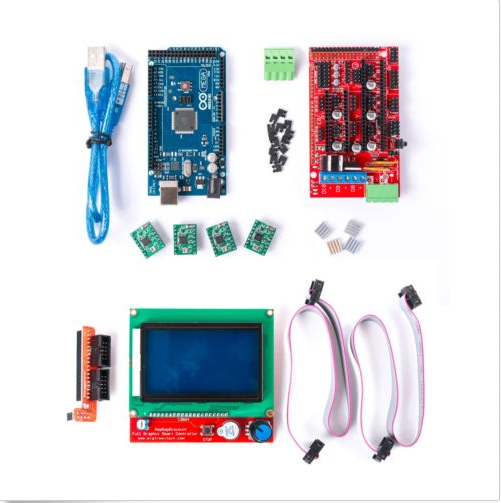
I started with this controller:
It's about $39 and includes:
- 1 x 1.4 RAMPS Arduino Shield
- 1x MEGA 2560 R3 16mhz Clone
- 4x A4988 Stepper Driver rated at 1A and cooling with up to 2A, Note: this board now comes with heat sinks.
- 1x 12864 LCD Screen with board with SD card interface
I guess it was a mistake, but they actually sent me 5 drivers. I won't have extruders, so apparently I only need 3, but I guess I'll have a couple extra in case I burn one up. In retrospect, I wish I had done an all-in-one controller like this one (arduino on the board). The shield might be better for tinkering, but for a production machine it will just make the box bigger and the wiring more complicated.
Motors ($80)
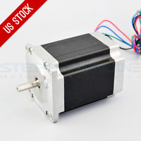
For motors, I went with NEMA 23 269oz stepper motors:
I paid about $80 for 3. Most of the other CNC build I've seen go a little bigger, but hopefully they should work okay for the X and Y access. If anything, I may just need something a little heftier for the Z axis (or add a second).
Hardware/Frame - 5/2/16 ($170)
I bought about $60 worth of hardware from MrMetric and around $110 worth of extruded aluminum for the Frame from Open Builds Store.
Filament ($22)
Bought my buddy Dave a roll of filament to print my parts for me.
Design
Controller
The RAMPS 1.4 controller setup involved:
- Join arduino/ramps.
- Add heatsinks to drivers
- Add jumpers to controller. For each stepper driver, there are 3 jumpers (6 pins). For 1/16th precision (recommended), configuration should be:
- Low end A4988 Driver: xxx (1 jumper on each set of pins)
- High end DRV8825 Driver: 00x (1 jumper on the far right pin)
- Install drivers in the XYZ positions
- Install LCD adapter and LCD
- Install 100ohm resistor on jumper T0 - this prevents a MAXTEMP error caused by a missing thermistor
- Download Marlin firmware
- Configure Marlin firmware
- Uncomment "#define REPRAP_DISCOUNT_FULL_GRAPHIC_SMART_CONTROLLER"
- Install u8glib library in Arduino IDE
- Compile and upload
- Download "Printrun-Win-Slic3r-10Mar2014" (user interface for RAMPS)
- Apply USB power and run Printrun
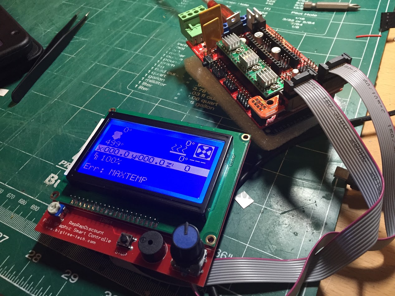
As you can see, I'm currently getting a temperature sensor error from the extruder (499 degrees is hot) and the compiler won't let me disable that sensor or remove the extruder. Currently researching how to work around this since I don't have an extruder (Note: temporarily fixed by adding a 100ohm resistor on T0 and setting TEMP_SENSOR_0 to -1). I suspect this firmware will work, but I may need to find a RAMPS firmware better suited to CNC. There seems to be an awful lot of stuff in the config that won't apply to me. Not to mention, my OCD kicks in when I see a non-existent extruder on the LCD.
Broken Z Axis on RAMPS board (4/21)
I was having a lot of problems with the Zaxis. It would stutter and make a lot of noise. It seemed like a power issue, but the current switch didn't seem to help and moving the same driver and motor to another position seemed to work fine. I assumed I had a bad board and even found what looked like cracked traces on the board near the Z axis. I contacted the vendor and they were nice enough to send me another one. Unfortunately it had the same issue. I toyed around with some of the settings in the firmeware and the problem seems to have gone away. Particularly I changed this line:
#define DEFAULT_AXIS_STEPS_PER_UNIT {80,80,80,500} // default steps per unit for Ultimaker
And set the steps to the same as the X and Y axis (I think it was set to 20 or 30 by default. Not sure why this had to be changed, but I'll research it more later.
Frame Construction
I was originally planning to do a CNC/3d Printer machine, but I've since decided to switch over to just 3d Printer. From what I've learned, it's difficult to make a good 3d printer that also does CNC. CNC needs to be slow, strong and heavy, and 3d needs to be light, fast, and agile. My thinking is that once I have a basic 3d printer, it will be easier to do more sophisticated projects in the future.
Build Selection: D-Bot (5/2)
I've decided to build a variation of the D-Bot build, however, I'm going to try and use my NEMA 23 motors. I'm going to try and stick with a single NEMA 23 motor for the Z-axis, unless it just doesn't seem stable enough.
Build Selection Revisited (5/13)
Well, after a lot of back and forth, I changed my mind and am building a variant of the Ultimaker 2. This is a simpler design that takes up less room and is well suited for enclosure. Unfortunately I had alreadady purchased a lot of the d-bot parts, so I'm having to tweak the design a bit. I also bought a few things that I won't really need for the ultimaker, so this is going to end up costing me at least $100 more than it should have.
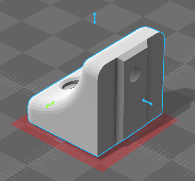
The good thing about this pivot is that it's given me an opportunity to really get in the weeds with Sketchup. The V-style rails of the D-bot are different than the Ultimaker, so I'm rebuilding many of the parts to fit these rails. Here's my first 3d part. This probably took about 10 hours to get working, which is sad because it's VERY similar to the original I built it from:
Notice the rail on the back that should add more support to the frame. Also notice the red foundation. I think that's a bad thing, but I'm not sure what it means (ignorance is bliss). My buddy Dave is doing a test print now so we'll see if it matters. The good news is that I'm finally starting to feel more comfortable in Sketchup and my second part went much quicker.
I still have some work to do, but here's my plans so far:
First Sketchup Part Created
It worked! It's very cool to see something you spent hours and hours imaging as a solid, functional part. Granted, my changes were minimal, but it's still a really good feeling. Not surprisingly, Dave did have some issues with the model, but after a couple tries he was able to get it to build.
VORON Sketchup
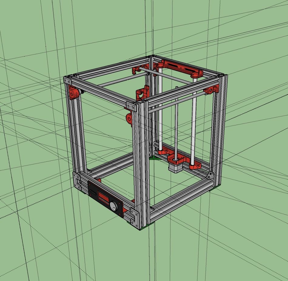
I've swapped builds again after having found a nice build on reddit called VORON by mzbotreprap. It's a corexy with most of the parts internal to the frame. It uses two motors and two lead screws on the Z axis to raise the bed, but I'm going to try and implement a cantilever design taken mostly from the T-Bot build (more for the challenge than anything else). I'll swap out the 8mm linear rails for something a little beefier and if it doesn't work out or seems unstable, it should be simple enough to fall back to the original design (might even throw a couple t-nuts in there just in case). I'm planning on shrinking the dimensions by 40mm (370mm vs 410mm) since I'm only planning to use a 200x200 bed and I also had to make some minor changes to the frame to accommodate the aluminum rails I already have.
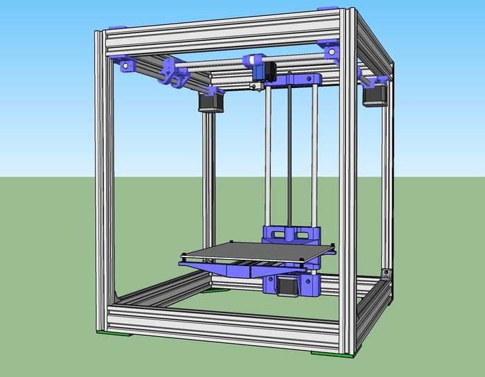
After many late nights (it's almost 4am), I'm really starting to enjoy working in Sketchup. I still have a ton to learn, but I'm getting there. Here's my design so far:
Made a couple tweaks to the design:
- The bed carrier was hitting the frame before it would get high enough to make contact with extruder. I reworked the carrier by centering the bed.
- I was only getting around 200mm build height, so I increased the Z height by 100mm to allow for taller builds. Related to this, I increased the linear rails to 10mm.
- I replaced the XY rails with 20x40 aluminum. Aesthetically, this will hide some of the internals, but the more pragmatic reason was that I didn't have enough 2020 aluminum after increasing the Z height.
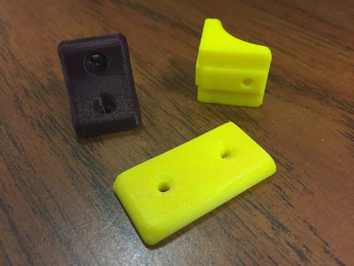
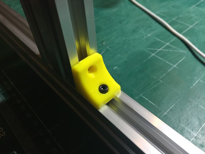
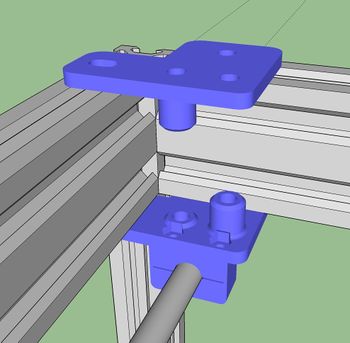
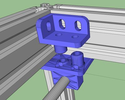
One of the few features of the Voron build that I wasn't crazy about were the brackets on the top holding the idler pulleys. The design puts almost everything inside the enclosure except these. When I started looking at how to work around this, I realized that by adding 40mm rails, I could now easily move these brackets down into the enclosure. I modified the bracket by cutting off it's tabs and adding some 90 degree supports that will screw directly into the top of the 40m rails. Of all the minor changes I've made, this is my favorite (assuming it works).
Notice that in the before and after, the distance between the two brackets is different. This is because when I switched to the 2040 rails, I forgot to account for the difference in rail size. Oops.
Almost Done
Or not..
Well, Dave sh*t all over my T-bot Z-axis implementation. He says he doesn't think the 3d printed parts will hold up well to heat. I think he just didn't want to print them (understandably), but he does make some good points. The T-bot page is mostly in german, and there aren't a lot of makes, so it's probably best not to dump a lot of time and money into it. Instead, I think I'm going to just go with an Ultimaker bed. It's a little more expensive, but there's definitely more people doing it, it will squeeze in fairly easily, and it seems like a good design. I found this nice thread discussing aluminum vs. glass and HPB (heated print bed) implementations.
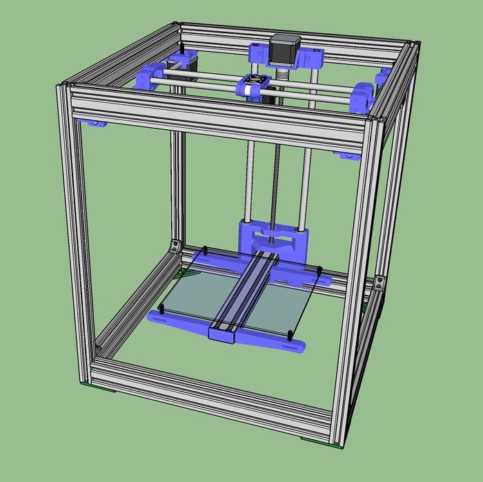
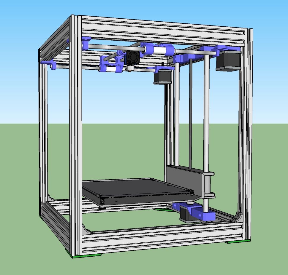
Voron/Ultimaker/T-Bot Hybrid
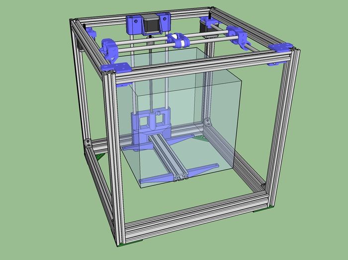
This design takes a little bit from everything. I'm using the aluminum frame/12mm linear rod design of the ultimaker, some Z-axis brackets from T-bot, and the CoreXY design from Voron. I actually like this design a lot. It's fully enclosable and combines the very popular ultimaker design with a solid corexy design. My one concern is that the Y rails are connected to the motor mount. It seems like this could potentially introduce vibration. It's also probably on the expensive side since it uses the expensive Ultimaker parts.
Setup
Simplify3D Configuration
M106 S0 ; Turn Fan Off
M104 S0 ; turn off extruder
M140 S0 ; turn off bed
G90 ; change to relative
G1 Z50 F3000 ; raise nozzle 20mm
G91 ; switch back to absolute mode
G28 X0 Y0 ;move X/Y to min endstops
M84 ; disable motors
Extruder Thermistor on SainSmart 2-in-1
While changing out my extruder, somehow I fried the thermistor pin for T0. It showed a constant 164 degrees even without anything plugged in. Fortunately I'm only using one extruder so I was able to swap the pins for T0 and T2 (T1 is the bed). This allows me to plug my exturder's thermisor into T2. I had some trouble figuring out how to do this in newer versions of Marlin, but in RC3, I was able to make it work by modifying pins_RAMPS_13.h to read:
#define TEMP_0_PIN         15   // ANALOG NUMBERING
#define TEMP_1_PIN         13   // ANALOG NUMBERING
instead of
#define TEMP_0_PIN         13   // ANALOG NUMBERING
#define TEMP_1_PIN         15   // ANALOG NUMBERING
