OrangePi: Difference between revisions
No edit summary |
|||
| Line 13: | Line 13: | ||
sudo ./build | sudo ./build | ||
</pre> | </pre> | ||
Documentation can be found in the man pages or here: http://wiringpi.com/the-gpio-utility/. | |||
And then tested: | And then tested: | ||
| Line 47: | Line 49: | ||
Use the table to determine the correct pin. The wPi column is the ID for the pin. Use: | Use the table to determine the correct pin. The wPi column is the ID for the pin. Use: | ||
<pre>gpio set mode out</pre> | |||
To set the mode. Once the mode is set correctly, use: | |||
<pre>gpio write 0 1</pre> | <pre>gpio write 0 1</pre> | ||
Revision as of 04:28, 13 April 2018
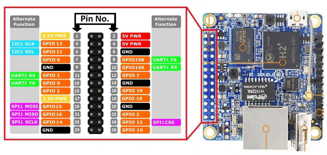
OrangePi Zero Pinout
Using GPIO w/ Orange PI
GPIO can be modified from the command line using WiringOP:
git clone https://github.com/zhaolei/WiringOP.git -b h3
cd WiringOP
chmod +x ./build
sudo ./build
Documentation can be found in the man pages or here: http://wiringpi.com/the-gpio-utility/.
And then tested:
gpio readall
 +-----+-----+----------+------+---+-Orange Pi+---+---+------+---------+-----+--+
 | BCM | wPi |   Name   | Mode | V | Physical | V | Mode | Name     | wPi | BCM |
 +-----+-----+----------+------+---+----++----+---+------+----------+-----+-----+
 |     |     |     3.3v |      |   |  1 || 2  |   |      | 5v       |     |     |
 |  12 |   8 |    SDA.0 | ALT5 | 0 |  3 || 4  |   |      | 5V       |     |     |
 |  11 |   9 |    SCL.0 | ALT5 | 0 |  5 || 6  |   |      | 0v       |     |     |
 |   6 |   7 |   GPIO.7 | ALT3 | 0 |  7 || 8  | 0 | ALT5 | TxD3     | 15  | 13  |
 |     |     |       0v |      |   |  9 || 10 | 0 | ALT5 | RxD3     | 16  | 14  |
 |   1 |   0 |     RxD2 |  OUT | 1 | 11 || 12 | 0 | ALT3 | GPIO.1   | 1   | 110 |
 |   0 |   2 |     TxD2 | ALT5 | 0 | 13 || 14 |   |      | 0v       |     |     |
 |   3 |   3 |     CTS2 | ALT3 | 0 | 15 || 16 | 0 | ALT3 | GPIO.4   | 4   | 68  |
 |     |     |     3.3v |      |   | 17 || 18 | 0 | ALT3 | GPIO.5   | 5   | 71  |
 |  64 |  12 |     MOSI | ALT4 | 0 | 19 || 20 |   |      | 0v       |     |     |
 |  65 |  13 |     MISO | ALT4 | 1 | 21 || 22 | 0 | ALT3 | RTS2     | 6   | 2   |
 |  66 |  14 |     SCLK | ALT4 | 0 | 23 || 24 | 0 | ALT4 | CE0      | 10  | 67  |
 |     |     |       0v |      |   | 25 || 26 | 0 | ALT3 | GPIO.11  | 11  | 21  |
 |  19 |  30 |    SDA.1 | ALT4 | 0 | 27 || 28 | 0 | ALT4 | SCL.1    | 31  | 18  |
 |   7 |  21 |  GPIO.21 | ALT3 | 0 | 29 || 30 |   |      | 0v       |     |     |
 |   8 |  22 |  GPIO.22 | ALT3 | 0 | 31 || 32 | 0 | ALT3 | RTS1     | 26  | 200 |
 |   9 |  23 |  GPIO.23 | ALT3 | 0 | 33 || 34 |   |      | 0v       |     |     |
 |  10 |  24 |  GPIO.24 | ALT3 | 0 | 35 || 36 | 0 | ALT3 | CTS1     | 27  | 201 |
 |  20 |  25 |  GPIO.25 |  OUT | 1 | 37 || 38 | 0 | ALT5 | TxD1     | 28  | 198 |
 |     |     |       0v |      |   | 39 || 40 | 0 | ALT5 | RxD1     | 29  | 199 |
 +-----+-----+----------+------+---+----++----+---+------+----------+-----+-----+
 | BCM | wPi |   Name   | Mode | V | Physical | V | Mode | Name     | wPi | BCM |
 +-----+-----+----------+------+---+-Orange Pi+---+------+----------+-----+-----+
Use the table to determine the correct pin. The wPi column is the ID for the pin. Use:
gpio set mode out
To set the mode. Once the mode is set correctly, use:
gpio write 0 1
To turn the flag off, and then:
gpio write 0 0
Python
Install PIP
sudo apt-get install python3-pip
Follow the instructions at https://opi-gpio.readthedocs.io/en/latest/
